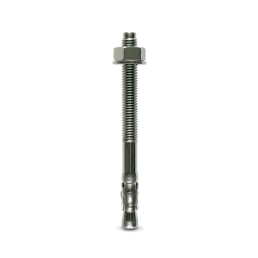
Bolzenanker
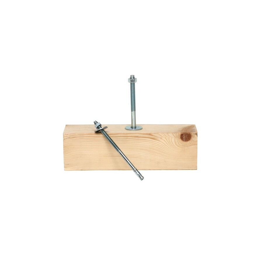
Spreizdübel M8 - M16 für Verankerungen im mittleren Lastbereich in ungerissenem Beton C20/25 – C50/60.
Produkt-Details
Eigenschaften
Material
- Stahl galvanisch verzinkt, passiviert
Vorteile
- Geringe Achs- und Randabstände
- Rationelle und wirtschaftliche Montage: vormontierte Mutter und Unterlegscheibe
- Verringerter Bohraufwand: Ø-Bohren = Ø-Gewinde
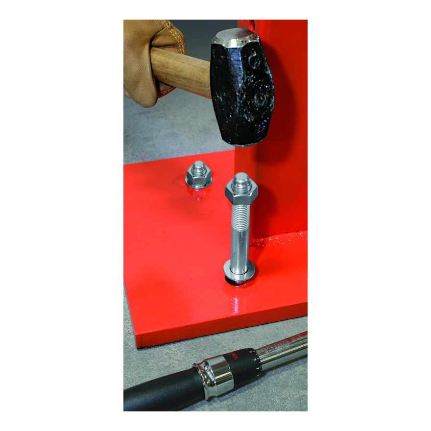
- Angeformter Schlagzapfen am Dübelkopf verhindert Beschädigung des Gewindes bei der Montage
Anwendung
Anwendbare Materialien
- Ungerissener Beton C20/25-C50/60
- auch geeignet für Naturstein mit dichtem Gefüge
Anwendungsbereich
- Stahl- und Metallbau (Konsolen, Fuß- und Kopfplatten, Rahmenelemente)
- Geländer, Tore, Treppen, Regalsysteme
- Kabeltrassen / Rohrinstallationen
- Anschluss von Holzverbindungselementen an Beton
Technische Daten
Abmessungen und charakteristische Werte
| Artikel | Bezeichnung |
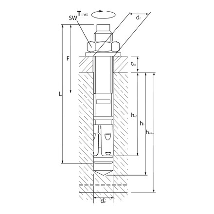
Gewinde- durchmesser [mm] | Ø Bohrloch x Bohrtiefe [d0 x h1] [mm] |
max. Klemmstärke [tfix] [mm] |
Ø Durchgangs- löcher im Anbauteil [df] [mm] |
Verankerungs- tiefe [hef] [mm] | Länge [L] [mm] | Gewindelänge [f] [mm] |
|---|---|---|---|---|---|---|---|---|
| WA M8-68/5 | WA8/5 | 8 | 8x65 | 5 | 9 | 45 | 68 | 40 |
| WA M8-73/10 | WA8/10 | 8 | 8x65 | 10 | 9 | 45 | 73 | 45 |
| WA M8-83/20 | WA8/20 | 8 | 8x65 | 20 | 9 | 45 | 83 | 45 |
| WA M8-93/30 | WA8/30 | 8 | 8x65 | 30 | 9 | 45 | 93 | 50 |
| WA M8-103/40 | WA8/40 | 8 | 8x65 | 40 | 9 | 45 | 103 | 50 |
| WA M8-113/50 | WA8/50 | 8 | 8x65 | 50 | 9 | 45 | 113 | 60 |
| WA M8-133/70 | WA8/70 | 8 | 8x65 | 70 | 9 | 45 | 133 | 85 |
| WA M8-163/100 | WA8/100 | 8 | 8x65 | 100 | 9 | 45 | 163 | 100 |
| WA M10-78/5 | WA10/5 | 10 | 10x70 | 5 | 12 | 50 | 78 | 40 |
| WA M10-83/10 | WA10/10 | 10 | 10x70 | 10 | 12 | 50 | 83 | 40 |
| WA M10-93/20 | WA10/20 | 10 | 10x70 | 20 | 12 | 50 | 93 | 50 |
| WA M10-103/30 | WA10/30 | 10 | 10x70 | 30 | 12 | 50 | 103 | 50 |
| WA M10-113/40 | WA10/40 | 10 | 10x70 | 40 | 12 | 50 | 113 | 60 |
| WA M10-123/50 | WA10/50 | 10 | 10x70 | 50 | 12 | 50 | 123 | 60 |
| WA M10-143/70 | WA10/70 | 10 | 10x70 | 70 | 12 | 50 | 143 | 70 |
| WA M10-173/100 | WA10/100 | 10 | 10x70 | 100 | 12 | 50 | 173 | 80 |
| WA M12-104/5 | WA12/5 | 12 | 12x90 | 5 | 14 | 65 | 104 | 60 |
| WA M12-109/10 | WA12/10 | 12 | 12x90 | 10 | 14 | 65 | 109 | 60 |
| WA M12-119/20 | WA12/20 | 12 | 12x90 | 20 | 14 | 65 | 119 | 70 |
| WA M12-129/30 | WA12/30 | 12 | 12x90 | 30 | 14 | 65 | 129 | 70 |
| WA M12-139/40 | WA12/40 | 12 | 12x90 | 40 | 14 | 65 | 139 | 80 |
| WA M12-149/50 | WA12/50 | 12 | 12x90 | 50 | 14 | 65 | 149 | 100 |
| WA M12-179/80 | WA12/80 | 12 | 12x90 | 80 | 14 | 65 | 179 | 110 |
| WA M12-199/100 | WA12/100 | 12 | 12x90 | 100 | 14 | 65 | 199 | 110 |
| WA M12-219/120 | WA12/120 | 12 | 12x90 | 120 | 14 | 65 | 219 | 125 |
| WA M12-239/140 | WA12/140 | 12 | 12x90 | 140 | 14 | 65 | 239 | 125 |
| WA M12-259/160 | WA12/160 | 12 | 12x90 | 160 | 14 | 65 | 259 | 125 |
| WA M16-171/50 | WA16/50 | 16 | 16x110 | 50 | 18 | 80 | 171 | 80 |
| WA M16-201/80 | WA16/80 | 16 | 16x110 | 80 | 18 | 80 | 201 | 100 |
| WA M16-221/100 | WA16/100 | 16 | 16x110 | 100 | 18 | 80 | 221 | 100 |
| WA M16-261/140 | WA16/140 | 16 | 16x110 | 140 | 18 | 80 | 261 | 110 |
.
Zulässige Lasten für Einzeldübel ohne Einfluss von Achs- und Randabständen 1) 2)
| Artikel | Ungerissener Beton C20/25 - C50/60 | zul. Biegemoment [Nm] | |||||||
|---|---|---|---|---|---|---|---|---|---|
| Zuglast [kN] | Querlast [kN] | ||||||||
| C20/25 | C30/37 | C40/50 | C50/60 | C20/25 | C30/37 | C40/50 | C50/60 | ||
| WA M8-68/5 | 5.7 | 7 | 8.1 | 8.9 | 5.4 | 5.4 | 5.4 | 5.4 | 13.8 |
| WA M8-73/10 | 5.7 | 7 | 8.1 | 8.9 | 5.4 | 5.4 | 5.4 | 5.4 | 13.8 |
| WA M8-83/20 | 5.7 | 7 | 8.1 | 8.9 | 5.4 | 5.4 | 5.4 | 5.4 | 13.8 |
| WA M8-93/30 | 5.7 | 7 | 8.1 | 8.9 | 5.4 | 5.4 | 5.4 | 5.4 | 13.8 |
| WA M8-103/40 | 5.7 | 7 | 8.1 | 8.9 | 5.4 | 5.4 | 5.4 | 5.4 | 13.8 |
| WA M8-113/50 | 5.7 | 7 | 8.1 | 8.9 | 5.4 | 5.4 | 5.4 | 5.4 | 13.8 |
| WA M8-133/70 | 5.7 | 7 | 8.1 | 8.9 | 5.4 | 5.4 | 5.4 | 5.4 | 13.8 |
| WA M8-163/100 | 5.7 | 7 | 8.1 | 8.9 | 5.4 | 5.4 | 5.4 | 5.4 | 13.8 |
| WA M10-78/5 | 7.6 | 9.3 | 10.7 | 11.8 | 8.8 | 9.7 | 9.7 | 9.7 | 27.1 |
| WA M10-83/10 | 7.6 | 9.3 | 10.7 | 11.8 | 8.8 | 9.7 | 9.7 | 9.7 | 27.1 |
| WA M10-93/20 | 7.6 | 9.3 | 10.7 | 11.8 | 8.8 | 9.7 | 9.7 | 9.7 | 27.1 |
| WA M10-103/30 | 7.6 | 9.3 | 10.7 | 11.8 | 8.8 | 9.7 | 9.7 | 9.7 | 27.1 |
| WA M10-113/40 | 7.6 | 9.3 | 10.7 | 11.8 | 8.8 | 9.7 | 9.7 | 9.7 | 27.1 |
| WA M10-123/50 | 7.6 | 9.3 | 10.7 | 11.8 | 8.8 | 9.7 | 9.7 | 9.7 | 27.1 |
| WA M10-143/70 | 7.6 | 9.3 | 10.7 | 11.8 | 8.8 | 9.7 | 9.7 | 9.7 | 27.1 |
| WA M10-173/100 | 7.6 | 9.3 | 10.7 | 11.8 | 8.8 | 9.7 | 9.7 | 9.7 | 27.1 |
| WA M12-104/5 | 12.6 | 15.4 | 17.8 | 19.5 | 14.3 | 14.3 | 14.3 | 14.3 | 47.1 |
| WA M12-109/10 | 12.6 | 15.4 | 17.8 | 19.5 | 14.3 | 14.3 | 14.3 | 14.3 | 47.1 |
| WA M12-119/20 | 12.6 | 15.4 | 17.8 | 19.5 | 14.3 | 14.3 | 14.3 | 14.3 | 47.1 |
| WA M12-129/30 | 12.6 | 15.4 | 17.8 | 19.5 | 14.3 | 14.3 | 14.3 | 14.3 | 47.1 |
| WA M12-139/40 | 12.6 | 15.4 | 17.8 | 19.5 | 14.3 | 14.3 | 14.3 | 14.3 | 47.1 |
| WA M12-149/50 | 12.6 | 15.4 | 17.8 | 19.5 | 14.3 | 14.3 | 14.3 | 14.3 | 47.1 |
| WA M12-179/80 | 12.6 | 15.4 | 17.8 | 19.5 | 14.3 | 14.3 | 14.3 | 14.3 | 47.1 |
| WA M12-199/100 | 12.6 | 15.4 | 17.8 | 19.5 | 14.3 | 14.3 | 14.3 | 14.3 | 47.1 |
| WA M12-219/120 | 12.6 | 15.4 | 17.8 | 19.5 | 14.3 | 14.3 | 14.3 | 14.3 | 47.1 |
| WA M12-239/140 | 12.6 | 15.4 | 17.8 | 19.5 | 14.3 | 14.3 | 14.3 | 14.3 | 47.1 |
| WA M12-259/160 | 12.6 | 15.4 | 17.8 | 19.5 | 14.3 | 14.3 | 14.3 | 14.3 | 47.1 |
| WA M16-171/50 | 17.2 | 21 | 24.3 | 26.7 | 26.9 | 26.9 | 26.9 | 26.9 | 111 |
| WA M16-201/80 | 17.2 | 21 | 24.3 | 26.7 | 26.9 | 26.9 | 26.9 | 26.9 | 111 |
| WA M16-221/100 | 17.2 | 21 | 24.3 | 26.7 | 26.9 | 26.9 | 26.9 | 26.9 | 111 |
| WA M16-261/140 | 17.2 | 21 | 24.3 | 26.7 | 26.9 | 26.9 | 26.9 | 26.9 | 111 |
1) Bei Interaktion von Zug und Querlasten (Hebelarm) sowie bei Dübelgruppen und / oder Randeinfluss ist eine Bemessung nach ETAG 001, Anhang C, Bemessungsverfahren A unter Berücksichtigung der gesamten Zulassung ETA-11/0080 zu führen.
2) Die Lastangaben berücksichtigen die in der ETA-Bewertung angegebenen Teilsicherheitsbeiwerte der Widerstände sowie einen Teilsicherheitsbeiwert der Einwirkungenvon γF=1,4. Bei den angegebenen Werten wird von unbewehrtem bzw. normal bewehrtem Beton mit einem Abstand der Bewehrungsstäbe s ≥ 15 cm oder s ≥ 10 cm bei einem Bewehrungsstabdurchmesser ds ≤ 10mm ausgegangen.
Installation
Installation
Befestigung
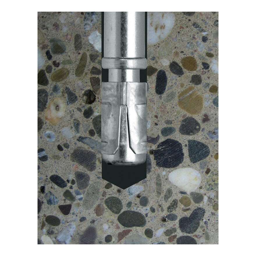
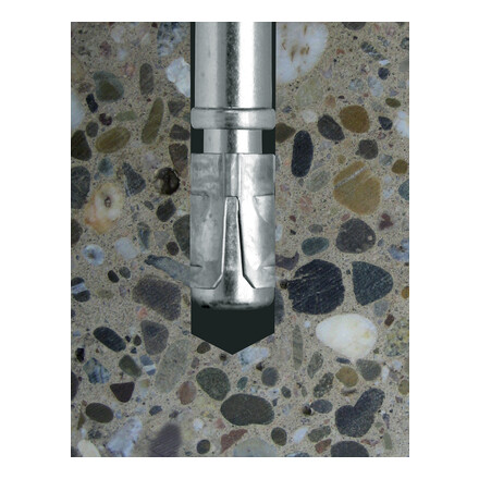
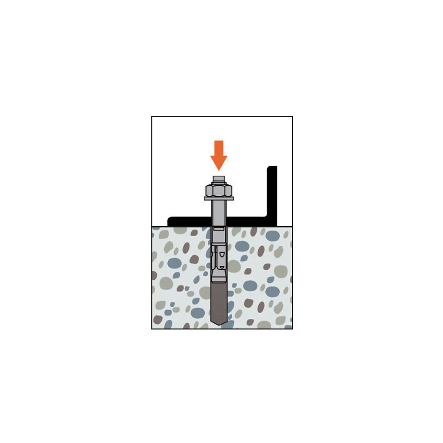
Bei Spreizdübelsystemen wird ein Konuselement in die Spreizhülse eingezogen und presst die Hülsensegmente gegen die Bohrlochwandung. Dadurch entsteht ein Reibschluss zwischen Bohrlochwandung und den Spreizsegmenten. Dieses Wirkungsprinzip ist geeignet hohe Lasten zuverlässig in den Ankergrund einzuleiten.
Montagedaten
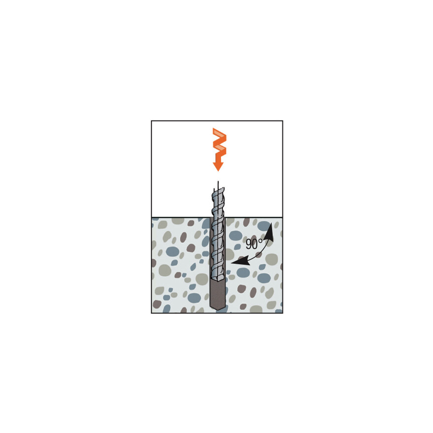
| Artikel | Ø Bohrloch [d0] [mm] |
min. Bohrlochtiefe [h1] [mm] | Ø Bohrloch [df] [mm] | Schlüsselweite [SW] [mm] |
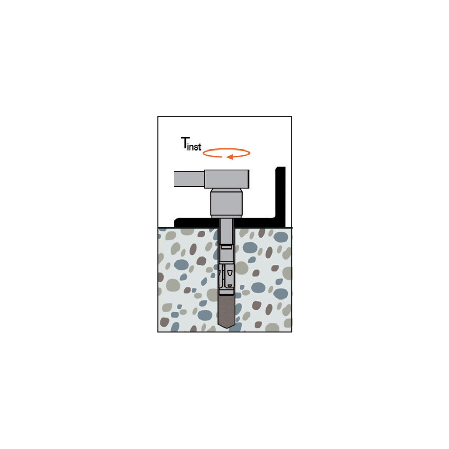
Montage- drehmoment [Tinst] [Nm] |
Verankerungs- tiefe [hef] [mm] |
Mindest- bauteilstärke [hmin] [mm] |
|---|---|---|---|---|---|---|---|
| WA M8-68/5 | 8 | 65 | 9 | 13 | 15 | 45 | 100 |
| WA M8-73/10 | 8 | 65 | 9 | 13 | 15 | 45 | 100 |
| WA M8-83/20 | 8 | 65 | 9 | 13 | 15 | 45 | 100 |
| WA M8-93/30 | 8 | 65 | 9 | 13 | 15 | 45 | 100 |
| WA M8-103/40 | 8 | 65 | 9 | 13 | 15 | 45 | 100 |
| WA M8-113/50 | 8 | 65 | 9 | 13 | 15 | 45 | 100 |
| WA M8-133/70 | 8 | 65 | 9 | 13 | 15 | 45 | 100 |
| WA M8-163/100 | 8 | 65 | 9 | 13 | 15 | 45 | 100 |
| WA M10-78/5 | 10 | 70 | 12 | 17 | 30 | 50 | 100 |
| WA M10-83/10 | 10 | 70 | 12 | 17 | 30 | 50 | 100 |
| WA M10-93/20 | 10 | 70 | 12 | 17 | 30 | 50 | 100 |
| WA M10-103/30 | 10 | 70 | 12 | 17 | 30 | 50 | 100 |
| WA M10-113/40 | 10 | 70 | 12 | 17 | 30 | 50 | 100 |
| WA M10-123/50 | 10 | 70 | 12 | 17 | 30 | 50 | 100 |
| WA M10-143/70 | 10 | 70 | 12 | 17 | 30 | 50 | 100 |
| WA M10-173/100 | 10 | 70 | 12 | 17 | 30 | 50 | 100 |
| WA M12-104/5 | 12 | 90 | 14 | 19 | 50 | 65 | 130 |
| WA M12-109/10 | 12 | 90 | 14 | 19 | 50 | 65 | 130 |
| WA M12-119/20 | 12 | 90 | 14 | 19 | 50 | 65 | 130 |
| WA M12-129/30 | 12 | 90 | 14 | 19 | 50 | 65 | 130 |
| WA M12-139/40 | 12 | 90 | 14 | 19 | 50 | 65 | 130 |
| WA M12-149/50 | 12 | 90 | 14 | 19 | 50 | 65 | 130 |
| WA M12-179/80 | 12 | 90 | 14 | 19 | 50 | 65 | 130 |
| WA M12-199/100 | 12 | 90 | 14 | 19 | 50 | 65 | 130 |
| WA M12-219/120 | 12 | 90 | 14 | 19 | 50 | 65 | 130 |
| WA M12-239/140 | 12 | 90 | 14 | 19 | 50 | 65 | 130 |
| WA M12-259/160 | 12 | 90 | 14 | 19 | 50 | 65 | 130 |
| WA M16-171/50 | 16 | 110 | 18 | 24 | 100 | 80 | 160 |
| WA M16-201/80 | 16 | 110 | 18 | 24 | 100 | 80 | 160 |
| WA M16-221/100 | 16 | 110 | 18 | 24 | 100 | 80 | 160 |
| WA M16-261/140 | 16 | 110 | 18 | 24 | 100 | 80 | 160 |
.
